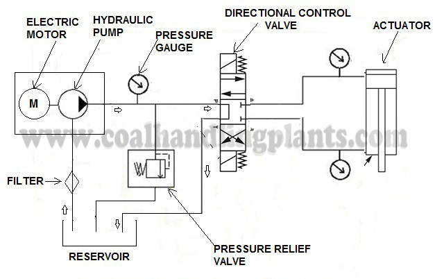
In a hydraulic system force that is applied at one point is transmitted to another point using a pressurized hydraulic fluid.
Hydraulic System Components And Hydraulic Circuit
1. Reservoir / Oil Tank
They are used to hold the hydraulic oil.
2. Hydraulic Pump
They are used to pressurized the hydraulic fluid and force the fluid through the system.There are three types of hydraulic pump:
I. Fixed Displacement Pump – These pump has a set flow rate means every stroke of the motor moves same amount of fluid. Fixed displacement pumps are perfect for single jobs that to be repeated indefinitely over long periods of time. There are three types of fixed displacement pump : Gear Pump, Gerotor Pump, Screw Pump.
II. Variable Displacement Pump – In Variable displacement pumps flow rate and outlet pressure can be changed as the pump operates. They are used to power a wider variety of tool, but require more expense and more attention. There are four types of variable displacement pump: Bent Axis Pump, Axial Piston Pump, Radial Piston Pump, Rotary Vane Pump.
III. Hand /Manual Hydraulic pump – These pump are operated by hand and foot.
Symbol Of Pump Used In Hydraulic System Circuit Diagram
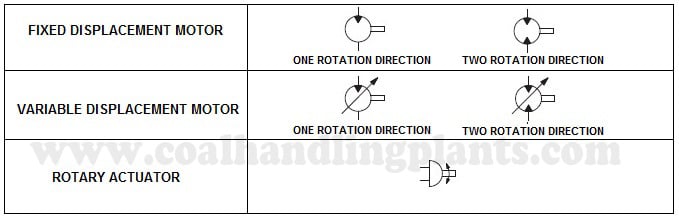
3. Hydraulic Motor
A hydraulic motor is a mechanical hydraulic actuator that converts hydraulic energy or hydraulic pressure into torque and angular displacement / rotation.
Types Of Hydraulic Motors And Their Symbol Used in Hydraulic Circuit Diagram
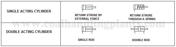
4. Hydraulic Cylinder
Hydraulic cylinder is a mechanical hydraulic actuator that converts hydraulic energy or hydraulic pressure into linear displacement. It consists of cylindrical barrel, piston and piston rod.
Types of Hydraulic Cylinder and Their Symbol Used In Hydraulic Circuit Diagram
5. Pressure Control Valve
Pressure control valves limit the system pressure to protect the system components. There are four types of pressure control valve:
I. Pressure Relief Valve – They are designed to protect hydraulic system when pressure in the system increases beyond the specified design pressure or maximum working pressure. They are normally closed and it opens when the pressure exceeds a specified maximum value and diverts the pump flow back to reservoir or tank internally. They are located near hydraulic pump.
II. Pressure Reducing Valve – They are design to limit and maintain outlet pressure. They are normally open and closed if the pressure exceed beyond specified design pressure at outlet. They are located near hydraulic actuator.
III. Sequence Valve – The sequence valve is used to ensure that a certain pressure level is achieved in one branch of the circuit before a second branch is activated.
IV. Counterbalance Valve – Counterbalance valves are used in hydraulic systems working with running-away or suspended load. They are designed to create backpressure at the return line of the actuator to prevent losing control over the load.
Symbol Of Pressure Control Valve Used In Hydraulic System Circuit Diagram
6. Flow Control Valve
A flow control valve is used for adjusting the flow rate of a fluid in a pipeline. The valve contains a flow passage or a port whose area can be varied.
Symbol Of Flow Control Valve Used In Hydraulic System Circuit Diagram
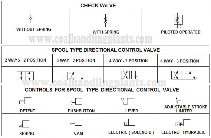
7. Directional control valve
Types of directional control valve.
I. Check Valve – check valve or non return valve are simplest type of directional control valve used to allow free flow of fluid in only one direction.
II. Spool Type Directional Control Valve – These valve are used to control the direction of fluid flow.
Symbol Of Directional Control Valve Used In Hydraulic Circuit Diagram
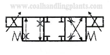
8. Proportional Valve
They are used in a hydraulic system that need to vary either flow or pressure to reduce lunge and shock.
Symbol Of 4 Way 3 Position Proportional Valve
9. Cheque Q Meter
They control the returning flow in relation to the flow being directed into opposite side of the actuator. It is used in hydraulic system to influence the speed of hydraulic motor and hydraulic cylinder independent to the load (prevent running away).
Symbol Of Cheque Q Meter
10. Solenoid Valve
It is a electro mechanically operated valve. The valve is control by electric current through a solenoid. The function of solenoid valve in hydraulic system is to shut off, distribute and release fluid.
Other Hydraulic System Components (Energy Transmission and Accessories) Symbol Used in Hydraulic Circuit Diagram Are:
Frequently Ask Questions of Hydraulic System
Q1. What is a Hydraulic System?
A hydraulic system is a power transmission system that uses pressurized fluid (usually oil) to generate, control, and transmit power for performing mechanical work. It follows Pascal’s Law: Pressure applied to a confined fluid is transmitted equally in all directions.
Q2. What are the major components of a hydraulic system?
Viscosity is the fluid’s resistance to flow. Correct viscosity ensures: proper lubrication, smooth flow, minimum leakage, limited temperature rise Too low → leakage, wear Too high → excessive power loss, poor response
Q5. What is cavitation in a hydraulic pump?
Cavitation occurs when vapor bubbles form and collapse inside the pump due to low pressure at the suction side. Symptoms: Milky oil, Pump noise (hammering), Vibration, Reduced discharge flow Causes: Clogged suction filter, High oil temperature, Low fluid level, Long suction line, Air leakage in suction line
Q6. What is aeration?
Aeration is the presence of air bubbles in hydraulic oil. Symptoms: Foaming, jerky motion, noise, high temperature. Causes: Loose fittings, cracked hoses, return oil splashing in tank.
Q7. What is a hydraulic accumulator?
A device for storing pressurized fluid to: absorb shocks, maintain pressure, assist pump flow, provide emergency power Types: bladder, piston, diaphragm.
Q8. How is pressure controlled in hydraulic systems?
Overheating, Low pressure, Slow operation, High noise, Jerky movement, Leakages, Pressure dropping under load, Cylinder drift
Q10. Why does a hydraulic cylinder drift?
Cylinder drift means the unwanted movement of a hydraulic cylinder rod without operator command. Example: A raised gate slowly coming down or a cylinder extending/retracting on its own. It is one of the most common faults in CHP equipment, paddle feeders, track hopper gates, wagon tipplers, and stacker reclaimers. It happen Due to: internal leakage through piston seals, valve spool worn-out, oil temperature increase, incorrect relief valve setting