In oil flooded screw compressor / oil injected screw compressor oil is injected to the compression chamber to cool and lubricate the compressor element and to reduce the return leakage to the intake.
Main Components Used In Oil flooded Screw Compressor / Oil Injected Screw Compressor
1. Air Filter Element
Air filter element are used to filter the air from dust and dirt.
2. Intake Valve Assembly
Before the air enters into airend, it passed the intake valve assembly. This valve opens and closes the air supply to the airend.
3. Airend
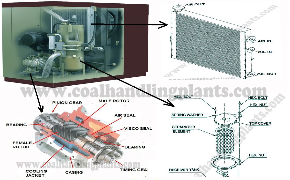
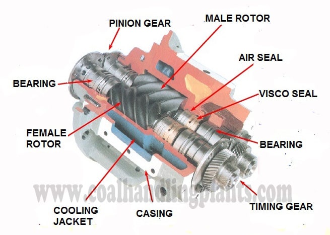
Airend is the main component of the compressor package in which atmospheric air is being compressed during the rotation of optimally designed twin helical screws. During compressing process oil is injected in the airend for lubricating and sealing off the clearances between the screws.The airend is coupled directly to the electric motor through a set of gears.
4. One Way Valve
The air-oil mixture leaves the airend through a one way valve. This valve sure that the mixture cannot flow back into the airend through the exit pipe.
5. Air / Oil Separator Tank
The function of air / oil separator tank is to separate the oil and air. Oil in the tank is first separated using a filter and remaining oil is removed using centrifugal force.
6. Minimum Pressure Valve
They are used to maintain minimum air pressure in air-oil separator tank so that positive oil flows is ensured. The valve is a spring loaded that opens at a certain pressure. The minimum pressure valve makes sure that there is always a minimum pressure inside the separator tank.
7. Safety Relief Valve
They are used to de-pressurize the compressor system if pressure exceeds beyond limits of the system.
8. Oil Level Indicator
This is mounted on air-oil separator tank. It gives visual indication of minimum and maximum level of oil present in compressor system.
9. Combi Cooler / After Cooler
The separated oil and air is hot due to absorption of heat during compression. These hot air and oil is cooled by the combi cooler / after cooler.
10. Moisture Separator
Due to cooling down of air in after cooler, a lot of water vapor has condensed against the inside of the after cooler. This water is carried with the compressed air.
The function of moisture separator is to separates the water from compressed air.
11. Oil Filter
The function of oil filter is to remove all the dirt and dust that has collected in the oil. It is fitted between the after cooler and airend.
Working Of Oil Flooded Screw Compressor / Oil Injected Screw Compressor
Air is sucked in by airend through the air filter and air intake valve. The air goes into the space between the interlocking screw. As the rotors turn, the air moves along and travels to other end of the compression chamber. During this compression process, oil is injected in the airend. The compressed mixture (air and oil) leaves the airend through a one way valve.
These mixture is then separated in air-oil separator. Some separated oil is collected at the bottom of the separator tank and is removed by the scavenge line and some oil is sucks back to the airend.
The clean compressed air which is separated from oil in air-oil separator tank is almost ready to leave the compressor but first passed the minimum pressure valve and the after cooler.
The separated hot oil is cooled by after cooler and again injected in the airend after passing through oil filter
Oil Flooded Screw Compressor / Oil Injected Screw Compressor Problems And Their Probable Causes
1. Problem – High Discharge Oil Temperature
Probable Causes – Cooler chocked either externally or internally, low oil temperature, room / ambient temperature too high, oil filter chocked, poor quality of oil, blockage in oil injection orifice in, malfunctioning of temperature sensor or valve, erratic reading showing in PLC.
8. Problem – Excessive oil in service line / consumption
Probable Causes – Clogged return line strainer or orifice, separator element damage or not function properly, leak in lubrication system, excessive oil forming, oil level too high.
9. Problem – Oil leakage through suction side when the unit is switched off
Injected oil performs: Cooling during compression, Sealing rotor clearances, Lubrication of rotors and bearings, Noise reduction, Contaminant flushing
Q2. What is oil carryover?
Oil carryover means excess oil escaping with compressed air, leading to: High downstream oil contamination, High oil consumption, Failure of separator element
Common reasons: Dirty coolers, Low oil level, High ambient temperature, Wrong oil viscosity, Thermostatic valve stuck, Blocked air filter, High duty cycle (continuous 100% load), Separator element clogged, Typical safe operating temperature: 75–95°C
Q4. Why does the compressor take too long to reach pressure?
Reasons: Leaking check valve, Worn rotors (low compression), Inlet valve not fully open, High separator pressure drop, Air leak in piping, Clogged air intake filter, Low oil level causing friction and slow rotation
Q5. Why is the compressor making high noise?
Possible reasons: Bearing failure, Rotor rubbing, Low oil level, Inlet valve flutter, Loose belt, Air leak, Unbalanced motor coupling
Q6. Why does compressor trip on high temperature?
Because: Oil cooler is dirty, Oil level too low, Wrong viscosity, Thermostatic valve damaged, High ambient temperature, Separator clogged, Motor overload, Continuous high load
Q7. Causes of low discharge pressure?
Worn screw rotors, Internal leakage in separator tank, Faulty MPV, Inlet valve malfunction, Air leakage in discharge line, Clogged air filter, High demand/load on system
Q8. What is unloading and loading in screw compressor?
Loading: Inlet valve fully open; compressor produces full air. Unloading: Inlet valve partially closed; compressor runs but produces minimal air to reduce wear. PLC cycles between load–unload to maintain set pressure.