
Forced Draft Fan (FD Fan) is a vital component of a thermal power plant, responsible for supplying the required amount of pressurized air into the boiler to sustain efficient combustion. It pushes ambient air through the air preheater and into the furnace, increasing the overall boiler efficiency by utilizing recovered heat from the flue gas.
This article explains the design, construction, working principle, control system, start-stop philosophy, alarms, and operating conditions of the forced draft fan.
Purpose and Function of Forced Draft Fan
The Forced Draft Fan (FD Fan) provides a positive air pressure inside the boiler system. Its function is to supply sufficient oxygen for complete combustion of fuel. Air drawn from the atmosphere is forced through an air preheater (APH) before entering the furnace, which improves the plant’s thermal efficiency.
By maintaining the necessary air flow and furnace pressure, the FD fan ensures stable combustion and uniform heat distribution throughout the boiler.
Design and Construction of Forced Draft Fan
Modern power plants generally use axial flow variable pitch fans, which operate at constant motor speed but offer variable airflow and pressure through hydraulically adjustable blades.
Its main components are: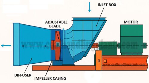
- Inlet Box
- Impeller and Casing
- Diffuser
- Hydraulic Pitch Control System
- Control and feedback loop
- Monitoring and Alarms
- Stall Protection System
- Motor and Coupling
All static parts like the inlet box, impeller casing, and diffuser are fabricated from steel and bolted together. The rotating components, such as the impeller blades and hub, are made from aluminum or spheroid graphite cast iron for strength and reduced inertia. The fan is insulated with mineral wool to minimize heat loss and noise.
Inlet Box
Designed to ensure uniform airflow across the impeller. It contains aerodynamic guide vanes, access doors for inspection, and a central lifting eye for maintenance handling.
Impeller and Casing
The impeller consists of multiple adjustable blades mounted on a central hub using blade holders, bearings, and control arms.
- Blade pitch can be varied hydraulically between minimum and maximum angles to regulate air volume.
- A control disc and hydraulic cylinder transmit movement to change the blade pitch.
- A bolted access door in the casing allows blade inspection and maintenance.
Main Bearing Assembly
The impeller shaft is supported by two anti-friction bearings housed together:
- Pilot bearing (motor side): takes both radial and thrust loads.
- Non-locating bearing (impeller side): takes radial load only.
- Bearings are lubricated by forced oil circulation from a common lubrication and hydraulic unit.
Diffuser
Converts kinetic energy into static pressure for efficient air delivery. It includes guide vanes, rotating union, and a position sensor linkage for feedback to the control system.
Hydraulic Pitch Control System

The pitch control system regulates the airflow by adjusting blade angles using hydraulic pressure.
Key Components are Hydraulic Unit, Proportional Valve, Rotating Union, Hydraulic Cylinder, Positioner and Limit Switches, Control Cabinet with Electronics
Working of Hydraulic Pitch control System
- The hydraulic unit supplies constant pressure oil to the proportional valve.
- The valve directs oil to either side of the hydraulic cylinder, which moves the control mechanism attached to the impeller hub.
- Blade pitch is varied by the axial motion of the piston.
- The positioner mechanism provides continuous feedback to the control cabinet, ensuring precise blade adjustment.
Control and Feedback Loop
When fan flow drops below the set value:
- The flow sensor sends a signal to the regulator.
- The control cabinet amplifier compares the command signal (desired pitch) with the actual signal (current blade position).
- A corrective signal is sent to the proportional valve, which moves the hydraulic piston.
- The impeller blades rotate to increase or decrease air flow until the actual and desired values match.
This closed-loop control system ensures stable fan performance and efficient boiler operation.
Monitoring and Alarms
All control functions are DCS-integrated and automatically monitored.
Typical Parameters Monitored
- Hydraulic and lubrication oil pressure
- Oil temperature and level
- Filter differential pressure
- Bearing temperatures
- Vibration signals
Stall Protection System
The FD Fan is equipped with a stall detection and protection system to prevent airflow instability or mechanical damage.
Principle of Operation and Control of Forced Draft Fan (FD Fan)
- The plant control system (DCS) sends a signal proportional to boiler load.
- The actuator adjusts the mechanical lever connected to the hydraulic cylinder.
- The hydraulic piston changes the blade angle, increasing or decreasing airflow.
- A feedback transmitter continuously reports the blade position for precise regulation.
This arrangement allows smooth and automatic air-flow control to match combustion demand under all operating conditions.
Start-Up Philosophy
Before starting the Forced Draft Fan, certain conditions must be satisfied:
Pre-Start Checks
- Adequate oil level in tank and temperature above 15°C.
- Oil pumps started and pressure ≥7 kg/cm².
- Proper lube oil flow to bearings.
- Actuator and blades set to minimum angle (around 16°).
- No alarm or trip conditions present.
Starting Steps
- Start oil system and confirm normal pressure and flow.
- Start the main fan motor.
- After reaching full speed, open the outlet damper and slowly adjust the blade pitch to meet furnace air requirements.
In systems with two FD fans operating in parallel, both should have equal set-points to maintain balanced air delivery and prevent stall.
Operating Conditions and Monitoring
During operation, several parameters are continuously monitored by the control system:
- Blade angle and actuator torque
- Bearing and winding temperatures
- Lubrication oil temperature and flow
- Vibration level of bearings
- Stall warning system signals
Stopping Procedure
Normal Stop
- Reduce boiler load gradually.
- Regulate the blade pitch to minimum position.
- Stop the main motor.
- Keep the oil pumps running until oil temperature drops below 40°C.
- Close the discharge damper after stopping.
Emergency Stop
- Cut power to the motor immediately.
- Keep the oil cabinet running until the system cools to a safe temperature.
Importance of Forced Draft Fan (FD Fan) in Boiler Efficiency
The Forced Draft Fan directly influences boiler performance and efficiency. Properly controlled FD fans:
- Maintain the correct air-to-fuel ratio for complete combustion.
- Support stable furnace draft pressure.
- Reduce unburnt carbon losses.
- Improve thermal efficiency of the boiler.
- Ensure long equipment life through smooth and balanced operation.