
Air Preheater in thermal power plant is a regenerative type heat exchanger designed to recover and utilize the heat that would otherwise be lost to the stacks of steam generating plants and process furnaces. By transferring the recovered waste heat to the cold combustion air, the Air Preheater is capable of saving a portion of the fuel that would have been required to heat the air to combustion temperatures in the boiler or furnace.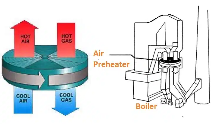
Components of Air Preheater in Thermal Power Plant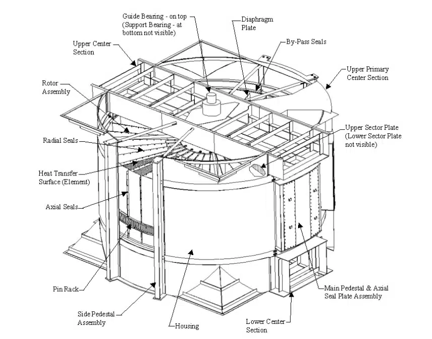
Air Preheater in thermal power plant consists of below mentioned components:
1. Rotor Assembly
The rotor assembly provides the structure for holding the heat transfer surface within the air preheater. It consists of multiple compartments arranged concentrically around a center shaft called the rotor post. Dividing plates, known as diaphragms, form the side walls of the compartments and also support the radial and axial seals.
The heat transfer surface is made up of thousands of specially formed sheets commonly known as “element”. The element sheets are factory packed into containers called “baskets”. The baskets are positioned inside the rotor arranged in hot and cold end rows know as “layers”. The baskets provide an easy method of installing and removing the heat transfer surface into and out of the rotor compartments.
2. Rotor Sealing System
Regenerative air preheater leakage does not affect thermal effectiveness, it does impact the size of the system fans and back-end equipment downstream of the air preheater. The necessity to minimize these effects resulted in the development of a sealing system capable of sustaining minimum levels of air-to-gas leakage.
The sealing system design accounts for the normal thermal growths of the air preheater rotor and structure to achieve effective sealing with a combination of rotating and stationary sealing members. The sealing system provides a wide range of seal adjustability with minimal maintenance requirements.
3. Rotor Drive Unit
The Rotor Drive Unit for the Air Preheater is designed for continuous operation. It consists of Speed reducer, main drive motor, standby drive motor, pinion gear and pinion air seal.
4. Guide Bearing Assembly
A radial spherical roller-bearing assembly guides the upper end of the air preheater rotor. The guide bearing is responsible for supporting the radial loads as a result of the air and gas flows through the rotor. The bearing assembly is lubricated by an oil bath to provide continuous operation and long bearing life.
5. Support Bearing Assembly
The Rotor is supported by a spherical roller bearing assembly, at the bottom of the air preheater. These components are responsible for supporting the loads generated by the dead-weight of the loaded rotor assembly and its supporting structure, as well as the radial load created by the pressure differential between the flue gas and combustion air ducts.
6. Retractable Soot blower
A retractable multi-media cleaner is used for on-line soot blowing of the air preheater heat transfer surface (element sheets). The cleaner is located in the flue gas outlet side of the air preheater to control deposit build up on the “cold end” heat transfer surface.
7. Water Wash Pipe
When the combustion deposit build-up on the heat transfer surface (element sheets) of the Air Preheater is such that it cannot be controlled or removed by a soot blowing device, it is necessary to off-line water wash the heat transfer surface to maintain acceptable pressure-drop through the air preheater. To supplement the cleaning abilities of the air preheater soot blower, the air preheater is equipped with stationary wash pipes.
8. Oil Circulating Unit
The air preheater is furnished with oil circulation units at the guide and support bearings. Because both the guide and support bearings are submerged in an oil bath, it is not necessary for the circulation units to be running continuously. The oil is circulated as required for periodic filtering and/or cooling.
9. Rotor Stoppage Alarm
The air preheater has been equipped with a Rotor Stoppage Alarm (RSA) to detect if the rotor stops turning, or slows to an unacceptable speed of rotation, for any reason. A proximity switch is mounted in the air preheater’s lower center section and is activated by vanes that are mounted on the main rotor shaft.
10. Leakage Control System
Air Preheater is a rotary regenerative heat exchanger, it is subject to air–to-gas leakage. This leakage is due to the thermal deformations of its stationary and rotating components and the pressure differentials between the air and gas streams. The portion of this air-to-gas leakage that passes between the radial seals and sector plates is called radial leakage.
To reduce the hot end radial leakage, Air Preheater is equipped with a Leakage Control System (LCS). In operation, the Leakage Control System will periodically move the hot end sector plates toward, or away from, the hot end radial seals to provide the smallest possible leakage path area. These “self-adjusting” sector plates provide an automatic leakage control system at all operating load conditions.
11. Temperature Monitoring Device
The purpose of the Thermocouple Temperature Monitoring Device (TTMD) system is to monitor the air temperature leaving the air preheater. When the TTMD system detects an unexpectedly high, local air outlet temperature, the system sends an alarm signal to the plant operators. This system is designed to allow the operator to investigate and take corrective action in advance of a major problem.
12. Deluge Pipe (For Fighting Fires)
The deluge pipes are used in conjunction with the stationary multi-nozzle wash pipes and other plant fire fighting equipment to help extinguish an air preheater fire. The system is design to emit large volumes of water onto a concentrated area of the heat transfer surface (element sheets).
Working of Air Preheater in Thermal Power Plant
It contains thousands of specially formed, and spaced, steel sheets. These steel sheets collectively make up the heat transfer surface, commonly referred to as “element”. The element is arranged in a cylindrical structure called the rotor. The rotor revolves slowly, within a structure that is separated into an arrangement of counterflow flue gas and combustion air ducts.
As the rotor rotates through the flue gas duct, spaces between the element sheets allow the gas stream to flow across the surface of each metal sheet. As the flue gas flows across the sheet, the element absorbs the waste heat that would normally exit the stack. As the rotor continues to rotate through the air duct, spaces between the element sheets allow the combustion air stream to flow across the heated surface of each sheet (in the opposite direction of the gas flow). As the air flows across the heated sheet, the element releases its heat to the incoming combustion air. Because the rotor carries the element alternately through the air and gas streams, the transfer of heat is continuous.
RELATED SEARCHES:
Steam Boiler in Thermal Power Plant