
Introduction
Flue gas desulfurization (FGD) is the removal process of sulfur dioxide (SO2) from flue gases. Sulfur dioxide in gases is produced by the combustion of fossil fuels and many industrial processes such as gasoline refining as well as cement, paper, glass, steel, iron and copper production.
Flue Gas Desulfurization (FGD) System Description
Flue gas desulfurization (FGD) consists of following systems:
- Limestone Preparation System
- Flue Gas & Absorber System
- Gypsum Dewatering System
Limestone Preparation System
Limestone preparation system in flue gas desulfurization (FGD) consists of following sub-systems:
1. Limestone Handling System
Limestone will be delivered to the limestone storage shed by truck. Limestone will be delivered from the limestone unloading hopper to the limestone day silo by limestone transfer conveyor and bucket elevator.
2. Reagent Preparation System
The reagent preparation system of flue gas desulfurization (FGD) includes a Wet ball mill and cyclone classifiers which produce a finely ground limestone slurry at 90% solids passing through 325 mesh. One mill slurry tank and one slurry pump is supplied for one wet ball mill.
The mill slurry pump will send limestone to ball mill classifier to classify big size limestone. Then, the overflow of the ball mill classifier shall go to the central slurry tank. The agitator is provided to keep the slurry solids in suspension during tank usage.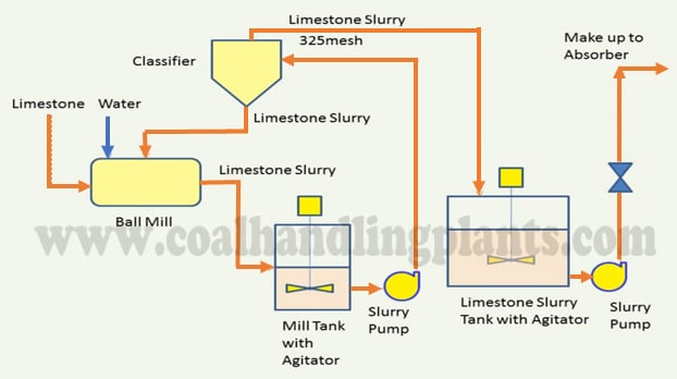
3. Limestone Slurry Storage Tank
Limestone slurry in the limestone slurry storage tank of flue gas desulfurization (FGD) system will be pumped to absorber by the limestone slurry feed pumps. The agitator is provided to keep the slurry solids in suspension during tank usage. Limestone slurry is added to the absorber to replenish limestone consumed by chemical reaction with the absorbed sulfur dioxide. The slurry addition rate is controlled by a pH control system based on the pH in the absorber.
Flue Gas System
Flue gas from the boiler ID fans will be transferred to one GGH (untreated side). The flue gas will then enter the flue gas desulfurization (FGD) absorber where SO2 is removed. And then, from absorber, treated flue gas will flow via the GGH treated side to the stack.
Note:
- GGH = Gas Gas Heater
- Flue gas treated by the absorber system will be reheated to prevent visible plume and corrosion of duct and stack and to improve the diffusion efficiency into the atmosphere.
Absorber System
Flue gas enters the absorber near the bottom of the spray-tower and flow upward to react with a descending spray of finely divided droplets of recycle slurry. The slurry contains the alkali needed to react with SO2.
Intimate contact of the flue gas with the alkaline limestone slurry is achieved in three successive spray zones. Each spray bank is provided with a series of spray nozzles designed to achieve proper automization of slurry.
Absorption system in flue gas desulfurization (FGD) consists of following equipment:
1. Absorber
The absorber reaction tank volume is adequately sized to provide sufficient retention time for limestone dissolution, oxidation of calcium sulfite to calcium sulfate (gypsum), and promte gypsum crystal growth.
2. Absorber Recirculation Pump
Each absorber recirculation pump is dedicated to a single spray bank. The absorber reaction tank is designed with sufficient delay time and adequate agitation to ensure optimum utilization of limestone and crystallization as well as precipitation of gypsum.
3. Oxidation Air Blower
Oxidation of calcium sulfite to calcium sulfate or gypsum is also accomplished in the reaction tank. Oxidation fans supply the air to lances submerged in the recycle tank for the oxidation reaction. The oxidation air is quenched with adequate amount of raw water to avoid nozzle plugging.
4. Mist Eliminator
A two-stage mist eliminator is provided at the top of the absorber. The first stage mist eliminator removes the bulk of the entrained liquid droplets from the gas stream. The mist eliminators are washed intermittently to maintain clean surfaces and low gas-side pressure losses.
Mist eliminator wash nozzles are located in the bottom and the top of the first stage mist eliminator and the bottom of the second stage mist eliminator. The frequency of the washing cycle is adjustable and is controlled based on the system water demand. A mist eliminator wash will utilize the make-up water coming from Make-up water tank.
5. Gypsum Bleed Pump
Gypsum bleed pump is provided to maintain 20 % suspended solids in the absorber. The main purpose of the gypsum bleed pump is to bleed off gypsum slurry from the absorber reaction tank to the gypsum dewatering system. Also, the gypsum bleed pump may be used to bleed off the slurry to the emergency storage tank during gypsum dewatering system trouble and FGD system maintenance.
6. Emergency Storage Tank
Emergency storage tank is equipped with one emergency tank pump to reclaim to collected slurry from the emergency storage tank to absorber reaction tank. The agitator is provided to keep the slurry solids in suspension during tank usage.
7. Absorber Area Sump
Drainage and flush water from pumps will be collected in the absorber area sump through trenches. One absorber slurry sump and one absorber area sump pump is provided for one absorber. The agitator is provided to keep the slurry solids in suspension during tank usage. The collected slurry in the absorber area sump will be returned to the absorber reaction tank or to the emergency storage tank.
Gypsum Dewatering System
A stream of slurry is taken from the absorber by gypsum bleed pump to remove the gypsum produced as a result of SO2 absorption and oxidation. The gypsum bleed from the absorber is fed to the primary hydrocyclone and then primary hydrocyclone underflow will be delivered to the vacuum belt filter.
The majority of the filtrate from the gypsum dewatering system is returned to the FGD system. With this flow, the unreacted limestone is thus sent back to the absorber to increase limestone utilization. Chloride concentration in the FGD system is controlled less than 6,000 ppm and delivered to existing plant to waste water treatment system by filtrate receiver pump.
Gypsum dewatering system in flue gas desulfurization (FGD) consists of following equipment:
1. Hydrocyclones
The hydrocyclone will be operated at a constant flowrate and consists of multiple clusters. Underflow from primary hydrocyclone to be 40~50% solids and overflow to be less than 5% solids. The overflow of primary hydrocyclone is return to absorber reaction tank or fed to secondary hydrocyclone feed pump. Overflow from secondary hydrocyclone is less than 1% solids. The overflow from secondary hydrocyclone is sent to waste water collection tank and underflow is return to absorber reaction tank
2. Vacuum Belt Filter
The vacuum belt filter shall produce the dewatered gypsum cake, which is contained less than 10% moisture. Vacuum belt filter system is consist of vacuum receiver, vacuum pump, cake wash tank, cake wash pump, cloth wash tank and cloth wash pump.
A distribution system is provided such that gypsum slurry from the primary hydrocyclone underflow is evenly distributed onto the moving belt. Belt is of the endless type and belt washing system will be provided to clean the belt after the dried cake has been discharged.
3. Reclaim Water Tank
Reclaim water tank is provided for absorber. The reclaim water tank pump is to reclaim filtrate water to limestone slurry preparation system and absorber reaction tank. The reclaim water tank is equipped with one emergency tank pump to reclaim to collected slurry from the emergency storage tank to absorber reaction tank. The agitator is provided to keep the slurry solids in suspension during tank usage.
4. Gypsum Dewatering Area Sump
Drainage and flush water from pumps will be collected in the gypsum dewatering area sump through trenches. The agitator is provided to keep the slurry solids in suspension during tank usage. The collected slurry in the gypsum dewatering area sump will be fed to the reclaim water tank or to the waste water collection tank.
5. Gypsum Handling System
The gypsum containing less than 10% moisture will be discharged from the vacuum belt filters to a conveyor belt where it is transported to the gypsum storage shed. The dewatered gypsum will be produced from FGD system, temporarily stored in the gypsum shed and discontinuously transported to offsite to load a truck by wheel loader.
Process Chemistry of Flue Gas Desulfurization (FGD)
In a wet limestone forced oxidized scrubbing system, a complex series of kinetic and equilibrium controlled
reactions occur in the integral absorber and reaction tank. These chemical reactions occur in the gas, liquid and
solid phases. The reactions may be stated in an overall expression as:
CaCO3 (limestone)+ SO2 (sulfur dioxide) + 2 H2O (water)+ 1/2 O2 (oxygen) → CaSO4•2H2O (gypsum) + CO2 (carbon dioxide)
RELATED SEARCHES:
Selective Catalytic Reduction (SCR)