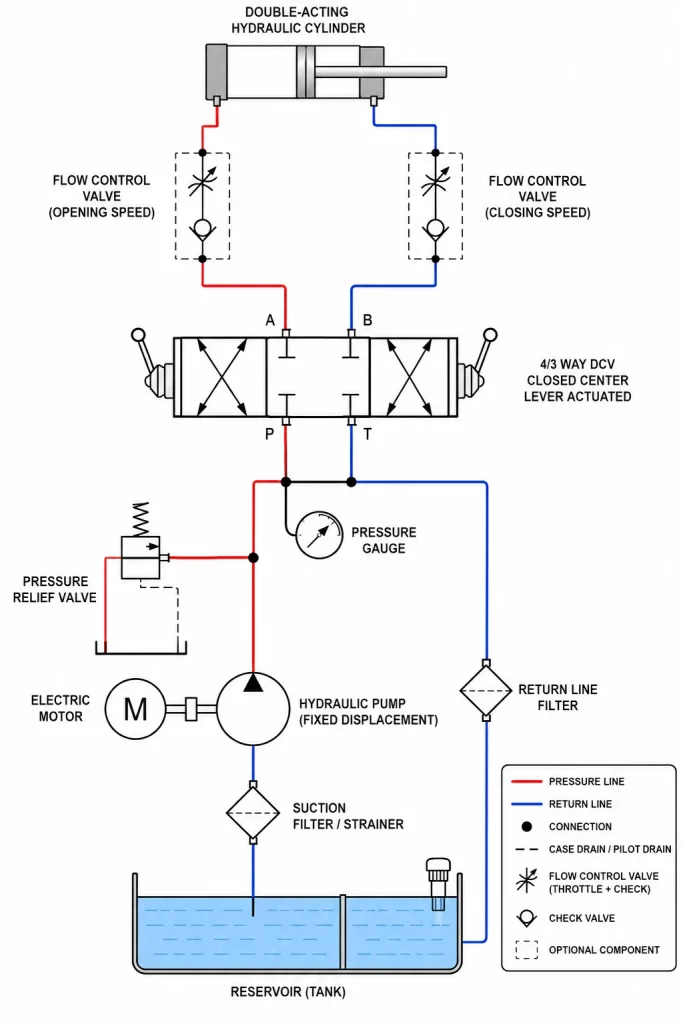
Draw a hydraulic circuit diagram using hydraulic symbology with the following components Power Unit:
Electric Motor: To drive the pump.
Hydraulic Pump (Fixed Displacement): To supply the required flow and pressure (e.g., a gear or vane pump).
Reservoir (Tank): To store hydraulic fluid.
2. Control Components:
Directional Control Valve (DCV): A \mathbf{4/3} way (4-port, 3-position) DCV with a closed center (or tandem center) and lever actuation (or solenoid actuation) is needed to control the cylinder’s direction and allow it to be locked in position when the valve is centered.
Pressure Relief Valve (PRV): To limit the maximum system pressure and protect components.
Pressure Gauge: To monitor system pressure.
3. Actuator:Double-Acting Hydraulic Cylinder: To perform the linear actuation that opens and closes the door.
4. Conditioning Components:
Filter/Strainer: To remove contaminants.
Check Valve: Used with the accumulator, if one is included, or sometimes in the PRV line.
Flow Control Valves (Optional): Two fixed or adjustable flow control valves (one for each line to the cylinder) can be added to precisely regulate the door’s opening and closing speeds.
5. Conductors:
Hoses and Piping: To connect all components.