Thruster brake is a device to retard the speed of moving machinery and to stop it accurately to the desired position.
Important Parts of Thruster Brake
Brake Shoe – The thruster shoe brake has a pair of cast iron shoes which are lined up with friction pads. The shoes are hinged on the main arm and the side arm of the brake, each of them having a hinge pin fitted in the base.
Lever Mechanism
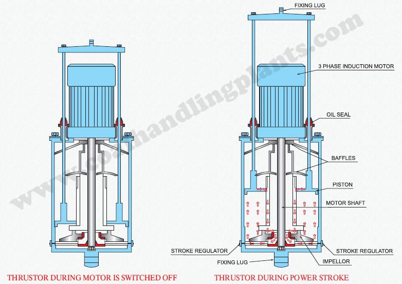
Thruster – It consists of 3 phase motor, bearing, oil seal, impeller, piston, stroke regulator, baffles and junction box.
Working Principle
Electrical power is used to rotate the impeller of thruster which in turn generates the hydraulic pressure by working on Oil hence to lift the piston. This smooth and jerk free thrust is either controlled by a appropriate stiff spring or counter weights of mechanical brake. Brake shoes are operated by brake mechanism, which is operated by thruster.
When the thruster is not energized, the brake shoes are pressed on the brake drum fitted on the drive motor shaft and hold it under the effect of braking force provided by the spring. In such a condition, the brake is applied and the drum cannot rotate.
When the thruster motor is energized, the thrust provided by the thruster lifts up the crank lever which moves the arms and the shoe brakes away from the brake drum, and releasing the braking force. The spring is compressed and braking energy is stored for the next cycle.
Work Involved During Preventive Maintenance Of Electro Hydraulic Thruster Brake
Check and ensure that thruster is lifted and brakes are released fully.
Check the brake shoe linings for any wear, if any damage is found, replace it.
Check that the brake drum surface must be free from grease, oil and other material.
Check the guide rods and cross bar should be cleaned and pin joints should be checked for free movement and lubricated by oil when necessary.
Check the oil condition and oil level.
Oil Filling Instructions
Fill the thruster with good quality transformer grade oil. Fill the oil through upper oil filling plug until it over flows. For removing air (if any trapped ), run the upward and downward strokes manually for several times and if oil level decreases, fill the oil until oil overflows. Oil once filled will last for long time, however when it’s required oil can be drained through bottom drain plug. While filling oil, thruster must be held vertically. Improper amount of oil in thruster will cause to insufficient pressure head, hence shorter stroke length. Ensure proper tightening of filling and draining plug after filling oil.
Frequently Ak Questions (FAQs) on Electro-Hydraulic Thruster Brake
Q1. What is an electro-hydraulic thruster brake?
An Electro-Hydraulic Thruster Brake (EHTB) is a fail-safe braking system used in conveyors, cranes, stackers-reclaimers, belt feeders, hoists, winches, and industrial machines. It uses: Electro-hydraulic thruster → creates lifting force Spring force → applies brake during power failure Brake applies automatically when power is OFF, making it fail-safe.
Q2. How does an electro-hydraulic thruster brake work?
POWER ON (Brake Released) 1. Thruster gets 3-phase power. 2. Motor turns impeller. 3. Hydraulic fluid pressurizes internal cylinder. 4. Ram/piston lifts the brake arms. 5. Brake shoes release the drum. 6. Machine runs freely.
POWER OFF (Brake Applied) 1. Power failure / emergency stop. 2. Thruster de-energizes. 3. Oil depressurizes. 4. Spring applies force on brake levers. 5. Brake shoes clamp the drum. 7. Machine stops safely.
Clearance depends on brake size. General method: 1. De-energize and apply brake. 2. Rotate adjusting nut/screws equally on both sides. 3. Maintain equal clearance between shoe and drum. 4. Re-energize thruster and check free rotation. 5. Re-check clearance under load. Typical clearance: 0.5 to 1.5 mm (depends on model).
Q6. Brake does not apply during power failure. Why?
Reasons: Faulty spring, Spring tension too low, Brake arms jammed, Pivots seized, Over-lubrication causing slip, Incorrect adjustment, Thruster stuck in UP position