Rotary coal sampling unit are used mainly in the coal industry to acquire samples of coal from a continuously moving conveyor belt.
Components Of Coal Sampling Unit
1. Primary Sampler
It consist of following parts:
Control Panel – A PLC based control panel controls the operation of the sampler.
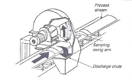
Housing – The main components of the housing are the top cover for the sampling arm and cutter, Dust cover to minimize pollution and spillage during the sampling action, mounting position for the sensor proximity switch, sample discharge chute.
Mounting Frame – The frame is usually mounted onto the existing conveyor stringers.
Motors and gearbox – The geared motors are supplied with a built-in, spring applied, electrical release brake on the rear of the motor. The brake will keep the swing arm in the parked position between 8 o’clock and 11 o’clock. This ensures that the swing arm is kept out of the stream on the conveyor belt. During the sampling action, the motor is energized via a PLC operated timer. The motor is switched off only once the sensor plate has passed the proximity switch.
Sampling Arm – The main components of sampling arm are arm extension, Swing arm with cutter, rubber scrapper, proximity sensor and proximity sensor shield.
2. Belt Feeder
The speed of the belt feeder used in CSU is relatively very slow which is acting as material feeding devices.
3. Crusher
Hammer mill types crusher are generally used in coal sampling unit.
4. Secondary Sampler
It consist of following parts:
Housing – The mild steel housing totally encloses the dividing plate, protecting it from unnecessary corrosion contains dust generation and enclosing all moving parts.
Divider Plate – The divider plate operated continuously rotated vertically through a 360 degree arc. The plate can be activated and de-activated by means of a sequence stop/start operation.
Geared Motor – The speed of the geared motor depends on the diameter of the dividing plate. It is designed to provide a cutter tip speed 0.6 m/sec. The motor shaft is coupled directly onto the hub of the rotating plate. A motor brake is fitted on some units to ensure that the cutter not stop in the path of the incoming feed and is parked in the 12 0’clock position.
Control Panel
5. Collector
It consist of following parts:
Sampling Container – Container is generally manufactured from SS-304 material with a low coefficient of friction, thereby ensuring no hand-up of material. The lid seals are air tight to prevent moisture loss.
Drive – A geared brake motor are used ranging from 0.25 KW to 0.75 KW as per requirement.
6. Screw Feeder / Screw conveyor
They are used to discharged excess coal from secondary sampler to plant conveyor.
Working Principle
The primary sampler consists of swing arm with cutter which rotates one revolution per cycle perpendicular to the coal flow. It cuts a swath through the coal and throws a sample into a chute which directly goes to the belt feeder and this belt feeder conveys the material to the crusher. The material is crushed to reach under screen size and material will pass to secondary sampler through the transfer chute. The sample coal from secondary sampler is finally collected in sampling container and excess coal from secondary sampler is discharges to other plant conveyor through screw conveyor.
Work Involve During Preventive Maintenance of Coal Sampling Unit
Check for any spillage.
Check the cutter for any wear, tightness and obstructions.
Check oil level, oil conditions, oil leakage of gear boxes.
Check for cleanness of equipments.
Check for proper operation of all equipments.
Coal Sampling Unit – Troubleshooting and Corrective Actions
Problem: Sampling arm is jammed and motor cannot turn
Cause: Oversize material or unwanted objects like steel or wood. Solution: Use brake lever on the back of the motor to release the cutter. Sampling arm can be moved manually.
Problem: The hammer sampling arm moves backwards from its parked position
Cause: The air gap on motor brake is incorrectly set, and/or the brake is worn. Solution: Reset air gap on brake and/or replace brake.
Cause: The direction of the motor is incorrect. Solution: Change direction by switching two phases.
Problem: On start-up, the sampler arm hangs in the 6 o’clock position while the motor is running
Cause: The phases have been incorrectly wired within the electrical control panel. Solution: Reverse phases.
Problem: During the hammer sampling action, the arm rotates (windmills) more than once
Cause: The proximity shield settings are incorrect. Solution: See page of Hot Commissioning.
Cause: The proximity sensor is faulty. Solution: Replace with a new proximity switch with 10mm detection range (usually open type).
Cause: The proximity sensor doesn’t detect the proximity shield. Solution: Move proximity sensor closer to the proximity shield. The distance between the shield and sensor must be between 5–10 mm.
Cause: There is no load on the belt. Solution: Check and adjust scraper and brush.
Problem: Swing arm is parked in the stream – at 6 o’clock
Cause: The proximity is faulty (LED light is not switching on). Solution: Replace the proximity.
Cause: The sampler has been incorrectly wired through the PLC system. Solution: Check wiring diagrams and correct the fault.
Cause: Sensor shields have shifted or are missing. Solution: Replace or reset the alignment of the shields and tighten bolts.
Cause: The distance between the proximity sensor and energizing plates is too great. Solution: See page in Hot Commissioning.
Cause: Solution: Move proximity sensor closer to the proximity shield for a gap of approximately 5–10 mm.
Problem: Hammer sampler does not operate
Cause: The motor direction is incorrect. Solution: Change direction by switching the two phases.
Cause: The power supply to the control panel is off. Solution: Switch power to control panel on.
Cause: The auxiliary equipment interlocks are faulty. Solution: Check the functioning of all auxiliary equipment interlocks.
Problem: Fines are not being completely removed from the conveyor belt
Cause: Brush and/or rubber scraper is missing. Solution: Replace with new rubber scraper and brush.
Cause: Hammer sampler clearance from the belt is too great. Solution: Remove packers and adjust clearance from the conveyor belt to the swing arm to between 5–10 mm.
Cause: Belt is tracking to one side. Solution: Adjust the tracking of the belt.
Problem: Excessive spillage is occurring during the sampling action
Cause: Rubber skirts are badly worn or are missing. Solution: Adjust and/or replace.
Problem: Continuous spillage is occurring around the hammer sampler structure
Cause: Belt is overloaded. Solution: Control the feed rate to the belt.
Cause: Hammer sampler is parked in the stream – at 6 o’clock Solution: See previous problem.
Problem: The overload trip lights indicate on the front of the control panel
Cause: Overloads have been set too low for the relevant motor amps. Cause: See hot commissioning Solution: The responsible electrician should reset or adjust as required.
Problem: There are blockages
Cause: There is excess moisture in the material causing high material viscosity and ‘stickiness’. Solution: Reduce if possible. If not, consider installing special, low-friction linings for the cutter and discharge chute work.
Cause: Tramp material – steel wires, logs, etc present in main process stream, especially ROM applications. Solution: Inspect and remove tramp material downstream of the hammer sampler. Connect metal detector and photoelectric cell in conjunction with the hammer sampler.