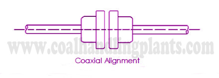
Shaft alignment is the process of aligning two or more shafts with each other to within a tolerated margin. The goal of the alignment process is to create a straight line through the coupling.
How is an alignment done?
The alignment of misaligned shaft are done by using different types of shaft alignment methods which are mention below :
Types Of Shaft Alignment Methods
- Rim and Face alignment method
- Straight edge alignment method
- Cross dial alignment method
- Reverse dial alignment method
- Laser alignment method
Rim and Face Alignment Method
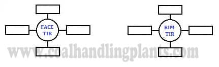
Rim and Face alignment method are oldest method used for shaft alignment of misaligned equipment/shaft. In this method two dial indicator ( rim and face dial ) are used to determine the relative position of movable shaft with respect to stationary shaft. The rim dial indicator is used to measure offset in one plane along the shaft length and face dial indicator is used to measure angularity or slope between the shaft.
Shaft Alignment Tool Set / Equipment Used During Rim And Face Alignment Method
- Dial Indicator
- Dial Indicator Stand with magnetic base / V-Brackets assembled with chains
- Extension rod
- Rod clamp
- Filler Gauge
Shaft Alignment Procedures ( Rim and Face Alignment Method )
The step by step procedure of rim and face alignment method is explained below :
- Measuring and documenting as-found misalignment conditions .
 Documenting is done on above diagram.To obtain a complete set of as-found readings, perform the steps below:
- Rotate the dial indicators to 12:00.
- Set the face dial indicator to zero.
- Record the setting of both dials at 12:00.
- Rotate the dial indicators to 3:00.
- Determine and record the reading on both dials.
- Rotate the dial indicators to 6:00.
- Determine and record the reading on both dials.
- Rotate the dial indicators to 9:00.
- Determine and record the reading on both dials.
- Rotate the dials to 12:00 and ensure that both dials return to their original setting.
2. Measuring vertical misalignment conditions
To measure vertical misalignment, perform the following steps:
- Rotate the dial indicators to 6:00.
- Set the face dial indicator to read zero.
- Rotate both shafts (if possible) to 12:00.
- Record the Rim TIR and Dial TIR .
- Interpreting Vertical Misalignment Data
To determine offset from the 12:00 TIR’s, use the following rules:
Coupling Offset = Rim TIR(Total Indicator Reading from the Rim Dial) / 2
3. Calculating the Front Feet and Rear Feet Positions
The position of the movable machine’s front feet is determined using the following equation

The position of the movable machine’s rear feet is determined using the following equation

Where,
- Face TIR = Total Indicator Reading from the Face Dial
- Rim TIR = Total Indicator Reading from the Rim Dial
- A = the diameter of the face dial indicator travel
- B = the distance from the Rim dial indicator plunger to the movable machine’s
- front feet bolt center
- C= the distance between the movable machines’ front and rear feet bolt centers
4. Making Vertical Corrections
- Positive values at the feet mean that the movable machine is high, therefore you will remove shims.
- Negative values mean that the movable machine is low, so you will add shims.
5. Making Horizontal Corrections
To correct horizontal misalignment by monitoring using dial indicators mounted at the
coupling, perform the following steps:
- Rotate the dial indicators to 9:00 and zero them.
- Rotate shafts to 3:00.
- Adjust the dial indicators to one-half their values.
- Move the front feet of the movable machine as you watch the rim dial indicator
move to zero - Move the rear feet of the movable machine as you watch the face dial indicator
move to zero. - Repeat steps 4 & 5 until both dial indicators read zero.
6. After Making Vertical and Horizontal Corrections obtain new reading.
RELATED SEARCHES:
Gear Coupling, Fluid Couling / Hdraulic Coupling,Bearing identification