Varaiable Speed Fluid Coupling | Scoop Coupling

Variable speed fluid coupling / Scoop coupling provides step less speed variation in a wide range when connected to fixed speed electric motor. The speed variation in variable speed fluid coupling / scoop coupling is obtained by varying the oil filling in coupling through a sliding scoop tube when in operation.

Important Parts Of Variable Speed Fluid Coupling / Scoop Coupling

SCOOP COUPLING PARTS

Assembly of Variable Speed Fluid Coupling / Scoop Coupling

Assembly of variable speed fluid coupling scoop coupling assembly

Upper Housing(1), Lower Housing(2), Reservoir Tank(3), Scoop Actuator(4), Breather Plug(5), Runner Shaft (6) ,Scoop Assembly (7), Primary Casing (8), Secondary Casing (24), Bearing and bearing housing assembly(9), Runner(10), Impeller(11), Oil Retaining Ring(12), Impeller bush and bearing assembly(13), Abutment Sleeve-Impeller Side(14), Circlip(15), Impeller shaft(16), Impeller Bearing Housing(17), Bearing(18), Abutment spacer-Impeller Side(19), Labyrinth Sealing Plate(20), Shaft Sleeve(21), Gasket(22), Oil Seal Sleeve(23), Abutment Plate-Scoop Housing(25), Bearing(26), Scoop Tube Housing(27), Internal Circlip(28), Guide Bush(29), Scoop Tube Bush(30), Guide Bush(31), U Seal(32), Support Bush(33), Scoop Tube(34), Abutment Sleeve-Scoop Housing(35), Bearing(36), Abutment Sleeve-Scoop Housing(37), Abutment Ring-Scoop Housing(38), Bearing(39), Lock Washer(40), Lock Nut(41), Labyrinth Seal(42), Shaft Sleeve(43), Gasket(44), Oil Seal Sleeve(45)

Related Link

Assembly of Fixed speed / Constant fill type fluid coupling, Basic working principle of fluid coupling

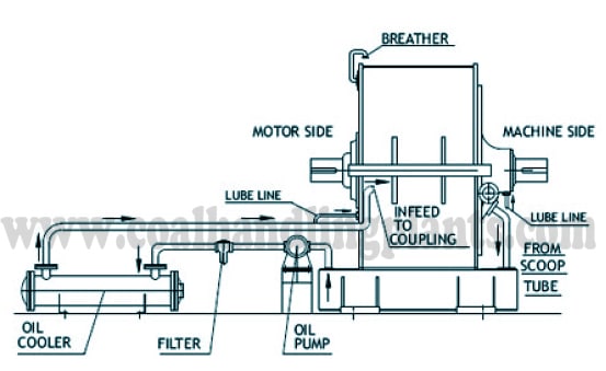
Oil Flow Circuit Diagram of Variable Speed Fluid Coupling Or Scoop Coupling oil flow circuit diagram of scoop coupling

The sliding scoop tube in this types of coupling governs the oil level in the working circuits depending on scoop tube Position between 0% to 100%. By varying the oil level in the working circuit the torque transmission capacity of the coupling varies, thus changing the slip of the coupling and provides step less speed variation in a wide range.

In 0% position, the scoop tube is at FULL In position and does not allow oil level to build up in the coupling. At this position of scoop tube, there is maximum slip and minimum torque transmission.

In 100% position, the scoop tube is FULL OUT position at which maximum oil is in circuit. This gives maximum torque transmission at minimum slip.

For intermediate position of the scoop tube, intermediate value of slip and torque transmission is obtained.

The heat generated in the coupling is picked up by the circulating oil which is cooled by oil cooler/ heat exchanger provided in the oil circuit.

Related Link

Basic working principle of fluid coupling/hydraulic coupling.

Advantage of Variable Speed Fluid Coupling / Scoop Coupling

  • Very low vibration and noise level.
  • Scoop tube position can be governed very easily for speed control.
  • Easy operation of scoop tube in auto or manual mode.
  • Labyrinth Seals on shaft ensures no leakage from shaft ends.
  • Smooth & controlled acceleration of heavy masses from stationary to running condition which improves service life of the motor.
  • High control accuracy and fast reaction times.

Fluid Coupling Application

  1. Material Handling : Belt Conveyors, Crushers
  2. Thermal Power Plant : Belt Conveyors, Crushers.
  3. Chemical Industry :Fans, Pumps, Mixers
  4. Oil & Gas Industry : Compressors, Pumps
  5. Metallurgical Industry : Blowers, Pump

RELATED SEARCHES:

Working of fluid coupling / Hydraulic coupling