In Line Magnetic Separator (ILMS) are used for continuous and automatic extraction or discharge of unwanted magnetic pieces (tramp iron) from the point where coal being discharged from conveyor.
Components of In Line Magnetic Separator
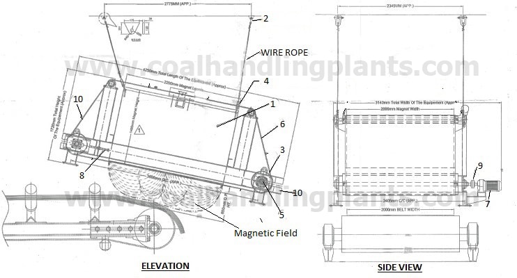

ILMS consist of below mention components:
- Electro Magnet
- D Shackle
- Pulley
- Turn Buckle
- Bearing
- Self-Cleaning Belt
- Drive Unit
- Belt Take-Up
- Coupling
- Aluminium Angle
In Line Magnetic Separator Installation
- ILMS should be mounted so that the magnet self-cleaning belt is at angle to the conveyor belt over which it is suspended.
- The electro magnet is parallel to the conveyor belt over which it is installed.
Working of In Line Magnetic Separator
Feeding of power supply to ILMS done before starting of conveyor belt. As power supply to ILMS ON, electro magnet is energized and self-cleaning belt of ILMS start rotating. After stating of ILMS, conveyor belt started. As the tramp iron comes along with conveyer material in magnetic field area which is created by electro magnet, the tramp iron is attracted towards the electro magnet. The ILMS self-cleaning belt will carry the tramp iron beyond the edge of the conveyor with the help of aluminium angle fitted in the ILMS self-cleaning belt. As the tramp iron gets beyond the magnet field it will drop off. Position of adjustable divider ensure that the trap iron does not fall back on the main conveyor. Finally, the trap iron discharge into a hopper through the divider.
Preventive Maintenance of In Line Magnetic Separator
- Magnet
- Check magnet case for any cracks and if there are cracks weld.
- Check the non-magnetic bottom plate for cracks and replace if necessary.
- Check oil resistance at established intervals.
- Check physical condition of all cables and leads.
- Use compressed air to clean off the accumulated minute magnetic particles on the face of the magnet periodically while the magnet is not energized.
2. Rectifier Control Panel
- Maintenance of this panel consist of regular inspection and cleaning application to similar types of electrical machinery and control equipment.
- Check cables and leads to and from the panel.
3. Gear Box
- Check oil level and top up with recommended lubricant.
- Keep the breather plugs clean.
- Regular oil changes are essential to ensure the unit gives long and trouble-free service. The frequency of oil change depends upon type of oil used, oil, temperature, environment and operating condition.
4. Self-Cleaning Belt
- Check the belt for sliprings, alignment and proper tensioning.
- Check the cleats (aluminium angle) on the belt.
- Check belt for wear on the inside or outside and the edges.
- To ensure longer belt life. Use compressed air to clean the belt thoroughly from the inside surface thus removing dirt, debris or metallic particles.
5. Pulley and Idlers
- Check the drive and driven pulley and idlers for alignment.
6. Bearings
- Clean the Plummer blocks and bearing of the pulley and idlers.
- Grease bearing as per recommended practice.
7. Belt Take-Up Unit
- Clean the sliding surface and the screw.
- Apply oil or grease as required.
Trouble Shooting
- Problem – Magnet will not attract
Case I
- Probable Cause – Magnet is not turned on or the magnet voltage is low.
- Solution – Check power switch D.C voltage or adjust as require.
Case II
- Probable Cause – Magnet is not installed at the proper suspension height.
- Solution – Check location of magnet with respect to burden and confirm that it is within the recommended suspension height at the centre line of the magnet.
Case III
- Probable Cause – Parts not being attracted are non-magnetic.
- Solution – Check missed tramp iron with small permanent magnet to confirm that it is magnetic.
Case IV
- Probable Cause – Induced iron in the area of the magnet prohibits the extraction of tramp iron.
- Solution – Check area around the separator with a small steel probe to see if the structure or conveyor components are themselves acting as a magnet and attracting iron. Replace with non-magnetic material as required.
- Problem – Fuses blow off immediately after switching on the magnet
Case I
- Probable Causes – Short circuiting in connecting cable
- Solution – Check for cable fault with ohmmeter, if necessary replace cables.
Case II
- Probable Causes – Earth fault in transformer rectifier panel.
- Solution – Check for earth fault in transformer with a megger/ohmmeter, if necessary replace transformer. Check for earth fault in panel, if necessary replace bad components.
Case III
- Probable Causes – Short in panel voltmeter
- Solution – Replace voltmeter
Case IV
- Probable Causes – Earth fault in magnet.
- Solution – Check for the earth fault at magnet terminals with a megger/ohmmeter. If it shows direct short, disconnect magnet leads from the terminals and check magnet coil insulation. If insulation of coils are above 2 mega ohms then replace terminal strips.
- Problem – Fuses in control circuit blowing
Case I
- Probable Causes – Contractor coil burn
- Solution – Replace contractor coil.
- Problem – No magnet power after switching ON magnet
Case I
- Probable Causes – Discontinuity in connecting cable cores.
- Solution – Check with multi meter for continuity and replace if found faulty.
Case II
- Probable Causes – Fuse links blown
- Solution – Check fuse links and replace them if necessary.
Case III
- Probable Causes – Broken connection
- Solution – Check the connection at all terminals
Case IV
- Probable Causes – Rectifier bridge blown
- Solution – Replace rectifier bridge.
Case V
- Probable Causes – Discontinuity in transformer
- Solution – Replace transformer
- Problem – Weak magnet power
Case I
- Probable Causes – Low voltage D.C due to low A.C supply voltage
- Solution – Measure supply voltage and adjust transformer primary taping accordingly.
Case II
- Probable Causes – Low voltage due to 2 phase, AC supply to the rectifier stack
- Solution – Check fuses and provide 3 phase supply to the rectifier stack.
Case III
- Probable Causes – Low D.C voltage defective rectifier stack
- Solution – Replace rectifier stack.
- Problem – Magnet over heating
Case I
- Probable Causes – Very high surrounding temperature
- Solution – Maintain normal ambient temperature at the place where the magnet separator is installed.
Case II
- Probable Causes – Magnet running on high D.C voltage than the specified for long duration.
- Solution – Maintain D.C voltage at the specified level.
Case III
- Probable Causes – Short in magnet coils
- Solution – Check current and coil resistance. If current exceeds the specified current, stop using magnet.
RELATED SEARCHES: